
See the system as a whole
The diagram below explains the broad roles of major components. It is a conceptual guide, not a manufacturer wiring diagram, service schematic, refrigerant routing plan or instruction to dismantle the appliance. Your model may arrange these parts differently.
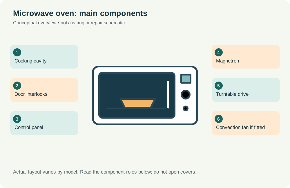
Main component roles
Use these names when describing the problem; do not remove covers to identify a part. The appliance label and owner manual are the appropriate starting point for exact model information.
| Component | What to understand |
|---|---|
| Cooking cavity | Contains food within the designed cooking space. |
| Door interlocks | Help prevent microwave operation with an open door. |
| Control panel | Accepts mode and timing inputs from the user. |
| Magnetron | Generates microwave energy in conventional microwave designs. |
| Turntable drive | Rotates the tray on models that use a turntable. |
| Convection fan if fitted | Circulates hot air in supported convection modes. |
Normal operating sequence
- Programme selected
- Safety interlocks checked
- Heating mode activated
- Timer ends programme
Controls coordinate the sequence and may pause it for safety or because a sensor detects an unusual condition. A stopped cycle or error message can have several causes. The diagram cannot identify a failed component without appropriate inspection.
What you can safely observe
Keep the cavity clean with manufacturer-approved methods and use containers suitable for the chosen mode. Never run the oven empty, bypass a door switch, remove its cover or attempt capacitor discharge. Unplugging does not make the internal high-voltage circuit safe.
Tell the technician what happens before the fault, which lights or codes appear and whether the problem is repeatable. Avoid guessing that a named component must be replaced because a similar symptom appears online.